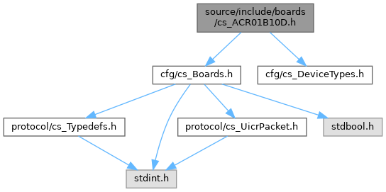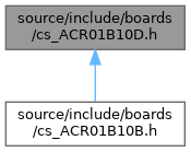

Go to the source code of this file.
Functions | |
| void | asACR01B10D (boards_config_t *config) |
| The ACR01B10D is also known as the Crownstone Built-in One. More... | |
Function Documentation
◆ asACR01B10D()
| void asACR01B10D | ( | boards_config_t * | config | ) |
The ACR01B10D is also known as the Crownstone Built-in One.
It comes with version v20 or the v25, but they are similar from a board configuration perspective.
The PWM enable pin might not be connected on the v20, but it is fine to be set nevertheless.
Reference voltage
- The reference voltage can be measured on pin P0.02 or (AIN0).
- It is created by a ADR280-1V2, which provides a stable 1.2V.
Measure current
- There are three possible gains to measure current. Mainly the lowest gain is used.
- There is a zero reference for the current (and voltage) and measures therefore differential.
Measure voltage
- This built-in has an offset as additional input for the ADC. It can do differential measurements.
- The ADC is configured with a range of -1.8V to 1.8V.
- Said otherwise, the ADC is configured with 1/3 gain.
- The voltage divider (R12/R13) centers at 3.3V/2 through two identical 68k resistors.
- The equivalent parallel resistor is 34k.
- The opamp gain becomes 34k/10.3M = 0.00330 (or 302.94x when inverted).
- If we divide 3.6V over 4096-1 we have 0.87912 mV per interval.
- The voltage multiplier of 0.00087912 * 302.94 = 0.26632.
- The difference between 3.3V/2=1.65V and 1.2V = 0.45V.
- That means there will be an offset of 450 / 0.87912 = 512. The voltageZero value. See: https://infocenter.nordicsemi.com/index.jsp?topic=%2Fps_nrf52840%2Fsaadc.html&cp=4_0_0_5_22_2&anchor=saadc_digital_output
TODO: Explain how it relates to: RESULT = (V(P) – V(N)) * (GAIN/REFERENCE) * 2^(RESOLUTION - m)
Temperature is set according to T_0 = 25 (room temperature) R_0 = 10000 (from datasheet, 10k at 25 degrees Celcius) B_ntc = 3434 K (from datasheet of NCP15XH103J03RC at 25-85 degrees Celcius) B_ntc = 3380 K (if we assume it to stay cold at for 25-50 degrees Celcius) B_ntc = 3455 K (if we assume it to become hot at 25-100 degrees Celcius) R_18 = 18000 R_ntc = R_0 * exp(B_ntc * (1/(T+273.15) - 1/(T_0+273.15))) V_temp = 3.3 * R_ntc/(R_22+R_ntc) See https://en.wikipedia.org/wiki/Thermistor#B_or_%CE%B2_parameter_equation.
We want to trigger between 76 < T < 82 degrees Celcius.
| T | R_ntc | V_temp | B_ntc |
|---|---|---|---|
| 25 | 10000 | 1.32 |
| 76 | 1859 | 0.3090 | 3434 | <- TODO: should be the used value | 82 | 1575 | 0.2655 | 3434 | <- TODO: should be the used value | 90 | 1256 | 0.2153 | 3455 |
Hence, 0.3135 < V_temp < 0.3639 in an inverted fashion (higher voltage means cooler).
Extras
- There's a pin which can be used to measure the 15V supply. It has a 324/80.6 voltage divider.
- It should be visible as a steady 15V * 80.6/(80.6+324) = 2.99V input on P0.05.
- The TX power is with -20 higher for the built-ins than for the plugs.